PRECESSION IN
WIND TURBINES
0. ABSTRACT
1. INTRODUCTION
2. RESONANCE
3. ANALYSIS of PRECESSION in a 2 BLADED
MACHINE
4. MODEL
5. INTERPRETATION
6. IMPLICATION
7. TWO BLADES?
8. SOLUTION to PRECESSION PROBLEM
9. CONCLUSION
10. ABBREVIATIONS
11. REFERENCES
by
Kali McLaughlin
Flowtrack P/L
P.O Box 5 Nimbin
ABSTRACT
Fatigue in wind turbines is discussed anecdotally, and "hub nodding" is analysed as an example of a forcing function able to stimulate resonances in tower structures. The issue of two versus three bladed turbines is raised.
INTRODUCTION
Having just lost two wind turbines which simply fell over, it is a good time for a paper on stresses in wind machines. Both machines were quite different, but both failed from fatigue in relatively mild conditions from a combination of stress multiplication by resonance, and stress concentration by poor structural design.
The point of this paper is not to hold forth on the relentless entropy of the universe and the toll of fatigue on all structures cyclically stressed. It is in fact the reverse, to claim that fatigue is NOT the problem it is often considered. Fatigue is often blamed for what is simply an inadequate appraisal of the stress levels in wind turbines.
The parts which failed in both the now recumbent wind turbines, were actually being stressed to near yield point, and the only surprise is that they lasted so long! With cyclic stresses kept to modest levels the materials used in wind turbines, steel, timber and fibreglass, can be almost immortal. Their cycle life is predictable and calculable (1). The performance of car springs is spectacular, and the life of aircraft is amazing considering the fact that aluminium, unlike steel, has a finite life at any level of cyclic stress. There is a tendency to regard fatigue failures as inevitable or inaccessible to prediction, rather than just one more design calculation (5).
The lay observer always wants things built heavier and stronger so that they look solid. This is often not the answer, as inertial forces are thus increased and resonance effects worsened. True stress levels must be either empirically measured, or calculated through a dynamic modelling of the reaction of a structure to the cyclic and steady forces disturbing it. It is in the nature of wind turbines to suffer slowly sweeping frequencies of exciting forces, and to have little damping in the tower. This can lead to large deflections from relatively small forces.
RESONANCE
In designing a structure it is necessary to know the force which will be applied to it, including its periodicity, the dynamic response of the structure, the analysis of stress distribution over the structure, and the fatigue properties of the material. Where multiple disturbances exist the worst case conjunction must of course be used.
An example of a force which adds to pre-existing ones is precession while the machine is yawing. While not a large force, it is transmitted through the turntable bearings in a fore-aft plane, creating a moment bending the top of the tower.
The reason that this force is significant is that it is not steady, but a pulsating force in a two bladed machine, and of double shaft frequency. This is likely to stimulate resonances in the tower, as described in previous papers (2).
ANALYSIS of PRECESSION in a 2 BLADED MACHINE
The textbook analysis of precession (3) starts with an angular momentum vector and then differentiates it to model a changing orientation. This leads to a moment which is steady and proportional to the rate of change of direction of the spinning object. This approach is not valid where an object has dissimilar angular momentum in different directions, as with a two bladed turbine.
To analyse a two bladed turbine the force on a single mass element "P" (eg one blade tip) is calculated as it describes a trajectory as in a yawing turbine.
MODEL
A kinematic approach is taken, with the turbine hub being located in x, y, z coordinates, the offset between the hub and the tower top being ignored in the interests of simplifying the mathematics. Further simplifications are made in assuming the rotational speed of the turbine, w, is constant, as is the rate of yaw, dq/dt. No scale is included at this stage, again in the interests of simplicity, giving a radius ‘r’ value of 1.
The model is later given data from the Flowtrack turbine as an example.
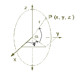
The locus of the blade element P can be defined by the intersection of the sphere
( for r = 1 )
| x˛ + y˛ + z˛ = 1 | (A) |
| y = x tan ( q ) | (B) |
which defines a vertical circle, and the rotation of the turbine can be described by defining the angle to the vertical a as wt where w is angular velocity of the turbine and t is time. The rate of yawing will of course be dq/dt in radians/sec.
To establish the forces necessary to send P on the described trajectory it is enough to find the second differential of the position of P with time, its vector acceleration and then multiply by the mass associated with P. This is simply Newtons Law:
| F = ma | (C) |
The position of P in x, y, z coordinates can be calculated from A & B solved simultaneously (or simply by inspection) to yield:
|
Px = cos ( a ) cos ( q ) Py = cos ( a ) sin ( q ) Pz = sin ( a ) |
(D) |
Point P can be made to rotate with time like a blade tip by replacing a with wt where w is the angular velocity of the turbine, this yielding:
|
x = cos ( wt ) cos (
q )
Py = cos ( wt ) sin ( q ) Pz = sin ( wt ) |
(E) |
Differentiating this expression with respect to time gives the expression:
|
dPx / dt = -w sin ( wt ) cos ( q ) - dq/dt cos ( wt ) sin ( q ) dPy / dt = -w sin ( wt ) sin ( q ) + dq/dt cos ( wt ) cos ( q ) dPz / dt = w cos ( wt ) |
(F) |
If the rate of yaw is constant, this simplifies the second differentiation to that below:
|
d˛Px / dt˛ = -w˛ cos ( wt ) cos ( q ) + 2w dq/dt sin ( wt ) sin ( q ) - (dq/dt )˛ cos ( q ) cos ( wt ) d˛Py / dt˛ = -w˛ cos ( wt ) sin ( q ) - 2w dq/dt cos ( q ) sin ( wt ) - (dq/dt)˛ sin ( q ) cos ( wt ) d˛Pz / dt˛ = -w˛ sin ( wt ) |
(G) |
This expression reduces to a much simpler form if we consider the moment when the rotation of the turbine is in the X-Z plane, q at this time being zero.
We can do this by appealing to symmetry and noting that there is nothing privileged in the choice of X-Y axes. All terms with sin ( q ) will then drop out leaving the expression:
|
d˛Px/dt˛ = -w˛ cos ( wt ) - (dq/dt )˛ cos ( wt ) d˛Py/dt˛ = -2w dq/dt sin ( wt ) d˛Pz/dt˛ = -w˛ sin ( wt ) |
(H) |
INTERPRETATION
We are looking at a time when P is moving in the X - Z plane and the acceleration in the z direction is that expected from the blades rotation : "-w˛ sin ( wt )".
The value in the x direction differs from the centripetal value of the Z direction by the term "(dq/dt )˛ cos ( wt ) " which however would be small, equal and opposite for the other blade at a point Q ( -x, -y, -z ).
The interesting term is that in the y direction which acts in the direction of blade lift.
There is no omega squared term here as there is of course no centripetal force in the direction perpendicular to the rotation. This acceleration is however proportional to the blade speed and yaw rate and modulated by the "sine omega" term which will make it vary with time as the point P rotates, becoming opposite when P is the opposite side of its circle. Although this acceleration of the opposite blade is in the opposite direction also, this only adds to the moment created on the turbine shaft, bending it in the vertical plane, at this instant the X-Z plane.
Moreover, although the acceleration appears to be at the frequency of rotation with its ‘sin ( wt )’ term, it is actually at double this, or blade frequency in a two bladed machine, because as the blade turns around to the opposite side its opposite force causes the same moment on the turbine shaft, having gone through a zero of acceleration on the way.IMPLICATION
If the model is scaled to the size of the Flowtrack turbine then some order of magnitude numbers are shown below :|
Term |
Description |
Value |
|
m |
Lumped |
2 kg |
|
r |
Radius of P from origin |
2 m |
|
dq/dt |
Yaw Rate |
1 |
|
w |
Rate of rotation |
30 rad/second |
An integration along the blade length incorporating the mass distribution is avoided here by lumping the outermost metre of the blade into a point at 2 metre radius as a first order approximation.
Then the force in the Y direction is
-2 m r w dq/dt sin ( wt ) = 240 Newtons peak.(J)
This is not a great force compared to the thrust force, but it is a significant additional load. The real danger is that it will pump other resonances in the machine. The moment created by this force on the blade root is 480 Nm extra stress on the blade cantilever, and if the blade flapping frequency were around 2 Hz and Q of say 4, then there is 2kN loading on top of the lift forces.
Another possible problem is that the moment created by both blades adds to apply 960Nm to the main turbine shaft, the gearbox feet, the turntable bearings, and all parts to the ground! Any lightly damped resonances in the whole structure will respond to this disturbance.
In lattice towers the bracing has been found to rattle annoyingly in spite of great efforts with blade balance and tracking. The easy answer is to use three blades instead of two, making the modulation of the precession force an order of magnitude lower.
TWO BLADES?
We are reluctant to go to three blades for one main reason: Our machine is stall governed. From this design decision it follows that we want a TSR of 10 so that the stalled torque is very low, allowing control in gales. A TSR of 10 means that the blades are very long and thin for best efficiency. A three bladed turbine with a TSR of 10 would have even thinner blades, and although they would each only have to bear 2/3 the thrust each, they would make for an even weaker cantilever than at present. Assuming the same aerofoil and pressure loading, the strength ratio would be the cube of the thrust ratio, or less than 1/3 the strength of a two bladed machine, necessitating a compromise in the aerodynamic section to improve strength against flexing.
In spite of the aesthetic superiority of three blades to most people, it would require compromise of efficiency, or loss of strength in what is the unavoidable compromise in a stall governed machine - the desirability of long thin blades to minimise thrust in deep stall, against the undesirability of long thin blades operating in cantilever.
It is easy to imagine the enormous centrifugal forces in a turbine at high speed, but in fact the destructive forces are the flexing forces caused by windage, and dynamic forces such as precession and blade flapping. The radial forces in fact are a surprising ally, providing centrifugal stiffening, and in helicopters actually used to carry most of the thrust by coning the hub.
SOLUTION to PRECESSION PROBLEM
The answer to many of the difficulties of two blades machines is almost too simple. If the machine yaws very slowly then the problems do not occur. Wind farm machines use servo controlled yaw, and some manufacturers of small machines are thinking the same way. The Flowtrack machine instead has a minimal tail area with a hinge to limit torque in the azimuth plane (4). This approach seems to have been adequate, Though there are still considerable yawing forces created by the differences in lift from blades skewed to the wind, and even without a tail the machine will follow the wind rather too well and even enter a mode of swinging from one side of the wind to the other.
Accepting that some precessional force is unavoidable, the next step in ameliorating the problem is to avoid any high Q resonances in the frequency range of usual operation. For this reason we designed the bipyramidal lattice tower which is extremely light and stiff so that the first flexing harmonic is above 10 Hz. The machine is designed to stop before this frequency is reached. Also, the resonance mode of the tower swinging about its base was intentionally reduced to less than 1 Hz, simply by leaving the guy ropes loose. This, as well as the shape of the tower, unfortunately offends peoples aesthetic taste!
With luck, fashion will prove more malleable than the laws of physics - just as cars of the 50's which looked aerodynamic to people of that era gave way to modern cars which are more aerodynamic.
CONCLUSION
The full analysis of the forces in a wind turbine is an extremely complex matter. The superposition of forces from various sources can add to far larger effects than steady state analysis might indicate. It is not fair to ascribe failures to fatigue when stress levels have not been evaluated.
The collection of real time data, and the forensic analysis of failure sounds like an unglamorous approach, but this procedure is what has made aircraft safe to fly. An iterative design methodology will no doubt work also with wind turbines, so long as design, manufacture, installation, maintenance and failure analyses are integrated.
ABBREVIATIONS
|
Term |
Description |
Units |
|
TSR |
Tip speed ratio |
none |
|
m |
Mass |
kg |
|
t |
Time |
seconds |
|
r |
Radius of P from origin |
m |
|
q |
Yaw angle |
radians |
|
w |
Rate of rotation |
radians / sec |
|
F |
Force |
Newtons |
|
a |
Acceleration |
metres/second˛ |
REFERENCES
Books
Resnick & Halliday "Physics" John Wiley,1960
Wahl, A.M. "Mechanical Springs" 2nd Ed McGraw - Hill Book Company
Conference Proceedings
McLaughlin K F "Report on E.F.N.H. Experimental Wind Turbine" Wind Energy Workshop, Monash University, 18/9/1995
Unpublished Papers
Uni of NSW Mech Eng lecture notes "Helical Spring Design" Jan. 1979
BEST P/L "Engineering Considerations of the Wind Turbine External Redesign and evolution of that design". Confidential report to Energy Australia 1998
Download this paper as zipped Word document, (about 17k).
1. Word 6
2.Word 97
![]()
ABN 68 079 207 168
0266 891431 (a/h)
0266 890408 (b/h)
OFFICE: End of Tuntable
Falls Road, NIMBIN